Among Seattle's lesser-known attractions is the Museum of Communications. I’ve been fascinated by the inner-workings of the telephone network about as far back as I can remember and upon learning of this place, I had to check it out. This all volunteer museum is open to the general public only on Tuesdays, so it’s a little tricky to arrange the time to visit, but I have managed to get there several times and collected numerous pictures. It seems a good subject for this blog. 
The museum features telephone sets spanning much of the history of the telephone, early data equipment, outside plant equipment, radio systems, recording devices, and much, much more; however my primary interest is the switching systems.

Central to the museum are a number of operational central office switches, technologies that were ubiquitous well into the 1980s. Today, very little of this equipment still exists anywhere; much less in working order. But here, the volunteers, mostly retired telecommunications workers who had operated systems like these for decades, have installed, restored, interconnected, maintained, and operated these switches for some years now.
When these systems were in widespread use, the telephone companies were very secretive about them. Few people outside of the telephone companies’ own employees ever got inside to see these things, and on the rare occasions when they did, seldom were able to get much information about how they worked. Here is an opportunity for anyone who ever wondered about this stuff to see it in operation, ask questions, and get answers as simple or detailed as desired.
Many years ago, I had the opportunity to visit inside a central office operated by the company then known as Pacific Telephone. In it, I found Step-by-step, Crossbar, and both #1 and #1A ESS systems. I’ve never forgotten the sounds, smells, and sights inside that facility.
Located in part of an active telephone central office building, the museum occupies space that would otherwise sit vacant, no longer needed in this day of ultra-compact switching systems and centralized plant administration offices. Due in part to this location, the experience captures what it was like inside central office installations that housed the types of equipment on display there.
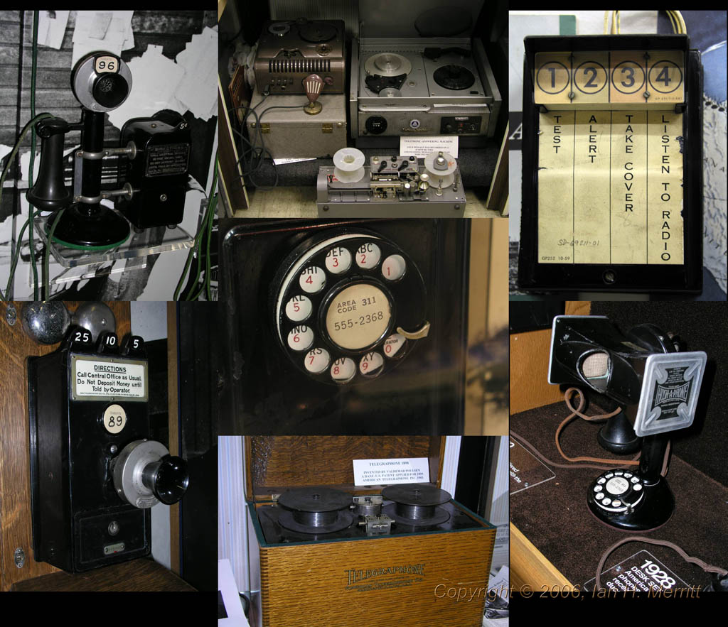
Manual switching
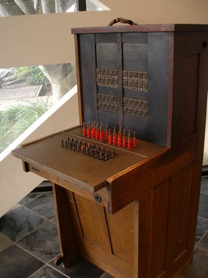
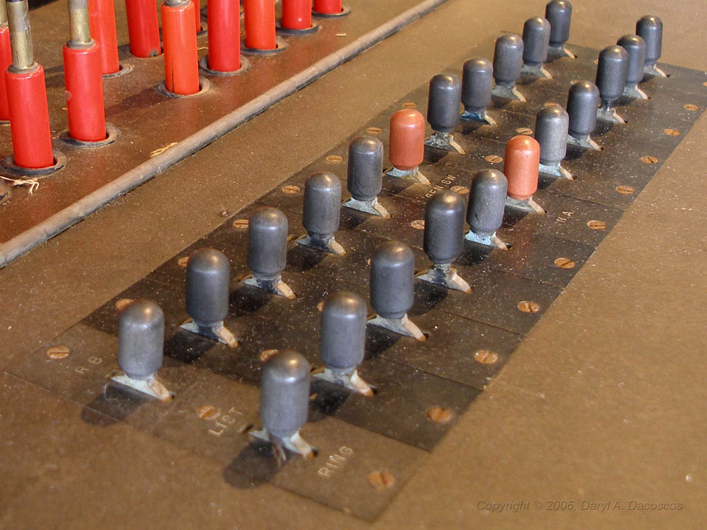
Switchboard images Copyright © 2006, Daryl A. Dacoscos
Early telephone systems were operated manually using switchboards consisting of jack panels, plug cords, a microphone/speaker mount in a handset or headset of sorts, and toggle switches that controlled what that set connected to.

To place a call, the caller (known in most relevant documentation as a subscriber) would turn the crank on a hand-operated magneto generator built into the telephone set which sent a 90-volt signal pulsing down the line toward the central office.

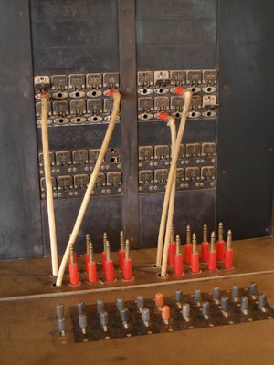
There, a small electromagnet was directly actuated by this voltage, unhooking a little metal tab causing it drop down, providing a visible (and persistent) indication that someone had tried to get the operator’s attention. Several of these tabs are seen in the dropped position in the image above.

As soon as the operator was able to attend to the line, she (nearly all telephone operators were women), selected an unused cord and plugged the ‘back’ plug into the line, flipping the toggle switch associated with that cord to connect her headset. If the party was still there, she’d say “number please”. If she’d been delayed before answering the line long enough that the caller had hung up, she’d toggle the switch over to the ring generator (which on some boards was crank-driven), and ring back, then switch again to her headset. If someone answered, she’d then ask if he wanted to make a call.
The subscriber might ask for a number served by the same office, in which case the operator took the plug on the other end of the cord, designated the ‘forward’ end, and plugged into the destination line; then toggled the switch to ring that line.

Letter suffixes were often used on the phone number to indicate a ringing pattern to identify which party on a multi-party shared phone line was the intended recipient of the call. Above is a page from the 1977 Avalon, California telephone directory. Avalon, the tiny town on Catalina Island, was the last manual office in the Bell System. In 1978, it was converted to electronic switching.
A caller would ask, for example, for 776J, as shown on the page above. After connecting to 776, the operator manually created the pattern of long and short ring pulses corresponding to the Morse code for this letter (J in the example would be one short then three long pulses of ring). Once the called party answered, the operator would (in theory at least) flip the switch to remove herself from the call.
After the call, the operator would tear down the connection by removing both ends of the cord. Weights attached below the console caused these cords to retract back into the panel.
If the subscriber wished to make a call to a line served out of another office, when the operator asked for the ‘number please’, he would say something like Magnolia 3474, identifying Magnolia as the serving office of the destination. If this office was adjacent to the originating office, there would be a few trunk lines connecting between the switchboards at the two offices. The operator would select one; insert her forward plug into it, and ring forward. The operator in the other office would answer and the originating operator would say 3474 please, whereupon the destination office operator would connect in the same way as described above for the intra-office call. When the parties hung up, both operators would recognize this condition and pull their cords, thus freeing the subscriber lines and the trunk line as well.
Toll and long-distance operation, once it became available, involved switching the call to another tier of operators who sent calls over regional and wide area trunk networks toward the destination office where an operator would connect to the destination line. These tandem offices worked similarly to the inter-office call except that more operators were involved as the call traversed more switchboards on its way. Toll and Long Distance offices had to maintain detailed routing information in a form that the operators could use to determine the next office along the route.
Long-distance transmission equipment also had to deal with significant loss over the distances involved. To the amplification equipment along the way, noise was indistinguishable from the signal (i.e. the parties’ voices); both were boosted equally. Callers had to shout to get over the accumulated amplified noise. The longer the distance, the worse the noise. Audio quality on these calls ranged from fair to unintelligible but in its day, it was a huge improvement over the time required to travel to meet people or send written messages via the postal system shipped by rail or whatever other transportation methods were available.
Automatic switching – Step-by-Step
As the story goes, automated telephone switching was first developed by a businessman, an undertaker as it happens, who was convinced, correctly or otherwise, that the human telephone operators were directing calls to his competitor. Almon B. Strowger proceeded to devise the Step-by-Step system of electromechanical rotary switches interconnected in such a way as to eliminate the need for the manual switchboard and human operator.
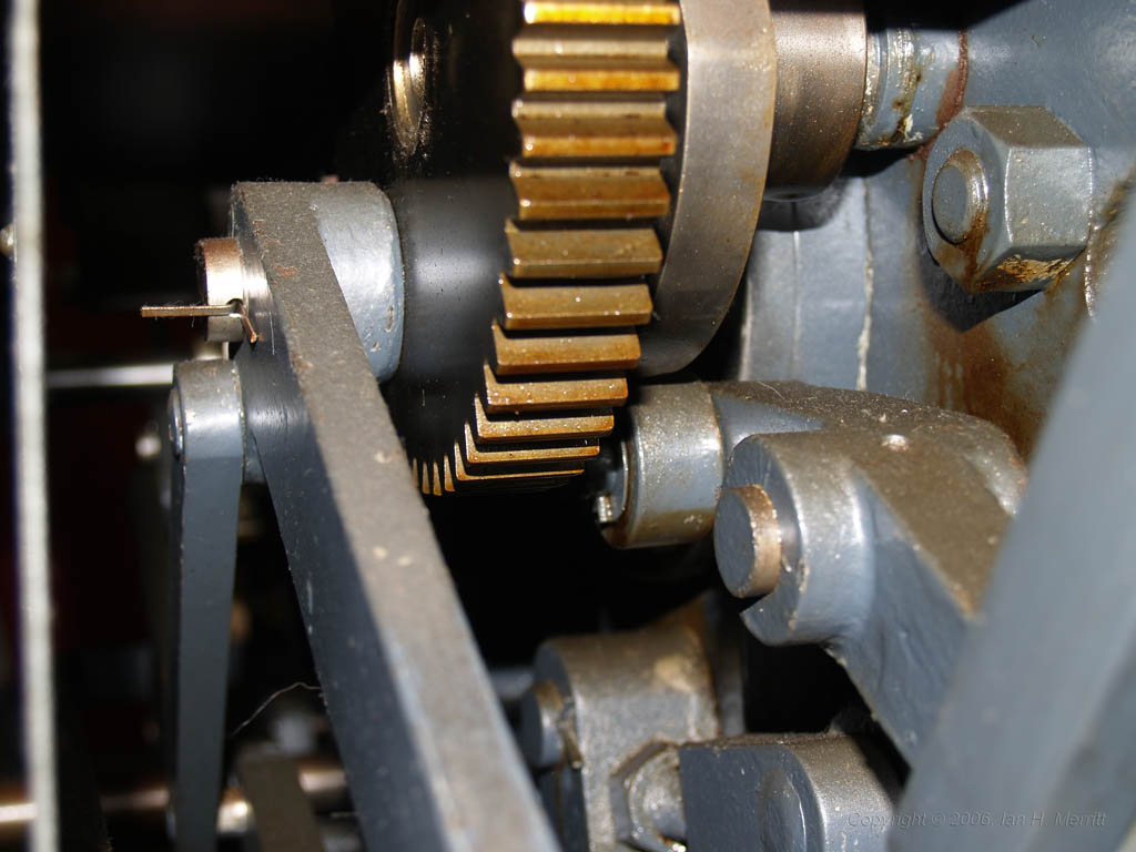
A step switch is a two-dimensional device typically configured in a 10 x 10 arrangement for a total of 100 positions; though different configurations were used for other functions. Depending on the specific function of the switch, it would have have one or more sets of contacts moving together. In response to signal pulses, the switch would first rise one notch at a time to reach the desired level; then rotate one position at a time to a specific contact.

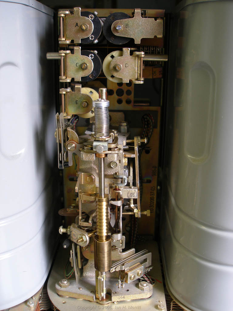
Individual contacts can be seen more clearly in this view.

This is the mechanism inside the metal can dust covers. The switch contact array is below the metal plate at the bottom of the image.
First widely deployed in the 1920s, some Step-by-Step systems were still in use into the early 1980s.
To place a call, the subscriber lifted the receiver (so-called because in those early phones, it was only the earpiece – the transmitter or microphone was fixed to the base of the telephone), and listen for a sound made by relay configured to oscillate like a buzzer. Upon hearing the dial tone, as it came to be called, the subscriber would proceed to dial a series of numbers using a rotary dial.

This dial was a spring-loaded rotary interrupter with a round plate with 10 finger holes, numbered 1, 2, 3 … 8, 9, and 0. A finger was inserted in the hole corresponding to the desired number and the rotor was turned against the force of the spring, toward a stop that protruded over the round plate, and then released. A one-way latch inhibited circuit interruptions during this forward motion. Under the power of the spring, with its speed damped by a centrifugal regulator, the released dial would slowly return to its home position. On the way, it briefly interrupted the telephone circuit at regular intervals the same number of times as the value of the number being dialed, with the exception of 0, which generated 10 pulses, since no pulses was indistinguishable from not dialing anything.

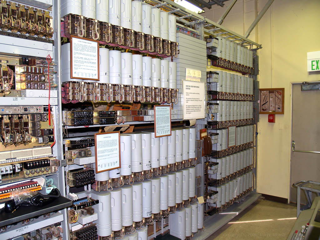
The Step-by-Step switching frame at the museum.
At the central office, when the receiver was taken off-hook, the first available of several Strowger switches configured as a line-finder, stimulated by the load change on the subscriber line, steps upward until it locates the line that has gone off hook. It then rotates to the position of the first available first-tier selector, another Strowger switch configured to respond to dial pulses.
The subscriber then dials a digit, causing the selector to step upward once for each pulse received in rapid succession from the subscriber line. A pause of longer than the maximum allowed pulse time started the selector rotating until it located an available selector at the next tier which in turn responded to the next dialed digit.
The final tier of switches in this sequence was called the connector. Similarly to a selector, the connector would step upward for each pulse in the second-to-last digit, but unlike a selector, the next digit caused the rotation which in turn connected to the called line, establishing a path through the switching matrix from the calling line to the called line.
Various other hardware provided ring, busy signals, howler tone to indicate a vacant line or other error, etc.
Subscribers could dial an office code to route to a line served in another office. The direct effect of this within the originating office was to switch the call to a trunk circuit connected to that other office and send the remaining dial pulses directly from the calling line to that other office, which would in turn complete the call. Toll and long distance calls still required an operator. Dialing the initial digit 0 would connect to an operator switchboard.
A variant of the strowger switch known as X-Y implemented essentially the same basic archicture but using a more compact switch in which both the X and the Y axes were flat enabling a higher density of switching. The museum does not have a working switching system based on this technology but has at least one example of such a switch unit.
Crossbar switching
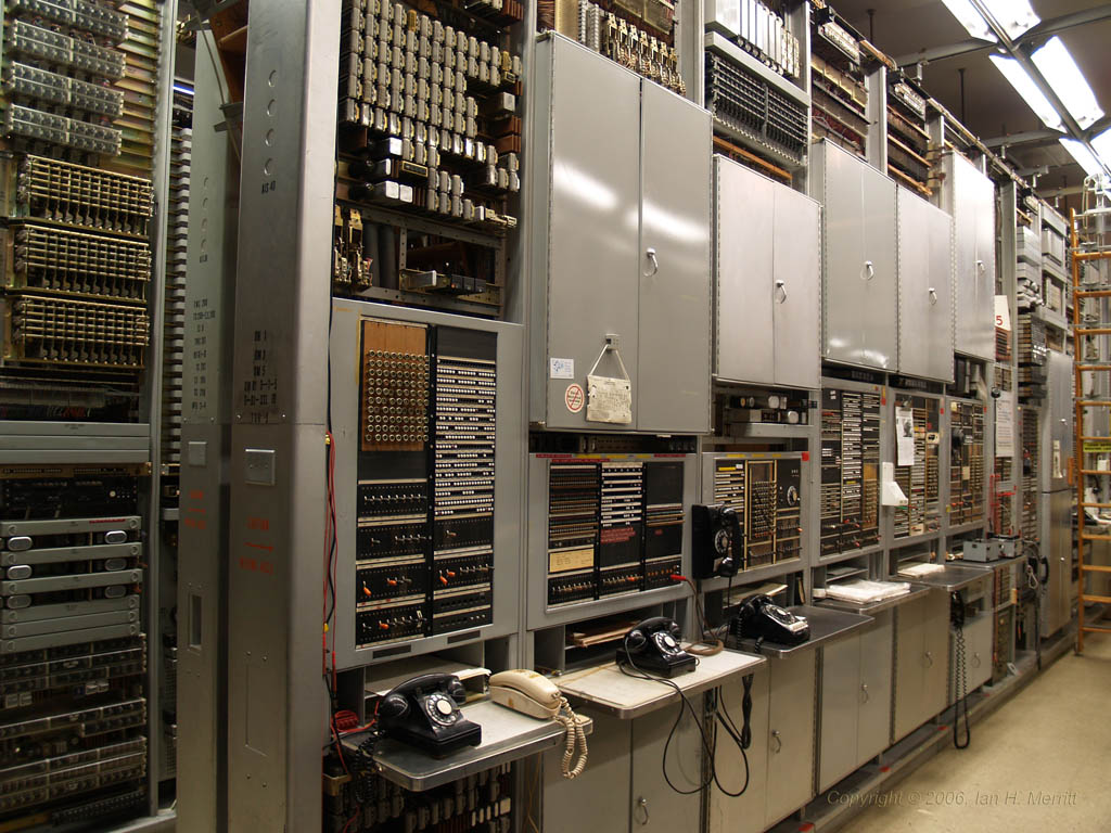
Much of the museum floor is occupied by a pair of working crossbar switches, a #1 and a #5. Still electromechanical, crossbar switches utilized a more compact switching array design and introduced the concept of common control. Implemented using the technology of the 1930s and 1940s, the same kinds of technology found in the adding machines and cash registers of the day and in card sorting machines used in pre-computer data-processing, the crossbar switching system employed a register to collect the string of numeric digits as they were dialed by a caller. Complex wiring panels were used to provide tables of how many digits to collect and how to route the call based on initial digit sequences.
The operation of the crossbar system is considerably more complex than the direct stimulus signaling in the step-by-step system and my understanding of it is quite limited, but here are some highlights.
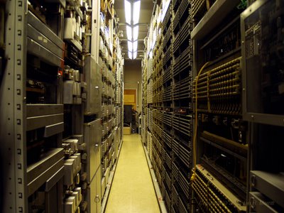
Crossbar equipment frames separated by very narrow access aisles.

Testboard on #1 crossbar.

Bank of relays on the #1 crossbar, part of a digit register or marker.

Originating register assembly on #5 crossbar switch. When a call is placed, this register collects the dialed digits. If the caller is using a dial phone, this device counts pulses; if a touch-tone phone, the decoded digit values are collected directly. Each time a digit is registered, it is stored in a bank of these relays. When sufficient digits have been collected, another machine called a marker, a primitive computer-like device, examines the collected digits and organizes control signals to effect a talk path across the switching matrix.

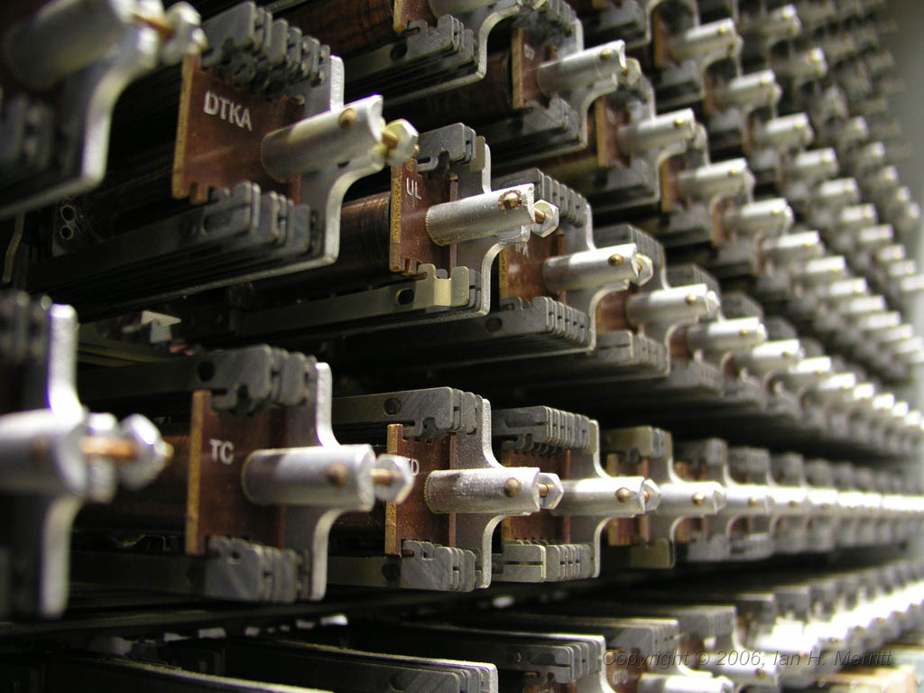
Close view of the type of logic relays used in the #5 crossbar originating register, marker, and terminating register.

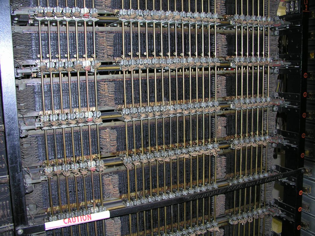
Crossbar switch modules within the #1 crossbar system.

A closer view of a crossbar switch module.
An extreme close-up showing contacts inside the crossbar switching unit.
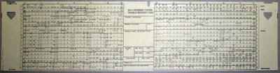
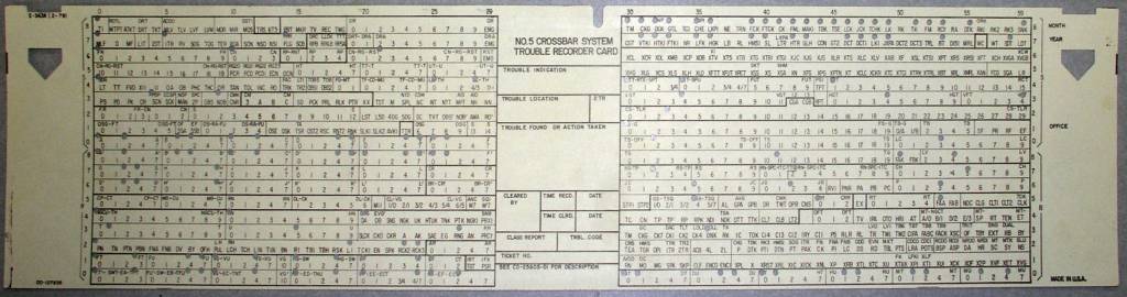
#5 crossbar switches introduced the trouble ticket. When the system detected an anomalous condition, it punched a card like this one, marking the form with holes that would be examined by a technician. In troubleshooting, it's often necessary to observe several failures before the cause becomes apparent. A clever aspect of the punched holes was that the tickets could be stacked and light would show through only the holes in common to all the cards in the stack. This helped to quickly identify what several failures might have in common.
Many more treasures
The pictures and information above dig a little bit into the area of telephone switching. The Seattle Museum of Communications has several other working switches including a system known as Panel, several small PBX-type switches of various generations, a #3ESS. There is plenty here to keep a telephone enthusiast interested. I have barely scratched the surface of how the crossbar systems operate. As time permits, I will return to this place and learn more about how these systems work, satisfying a curiousity I've had since I was a kid first using the telephone and observing the various sounds on the line. I may post again if I find something of interest.

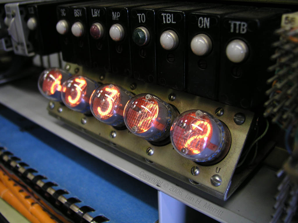
Nixie display tubes. These were neon tubs with a common cathode and 10 anodes cast in the shape of the numerals 0, 1, 2, through 9. When voltage was applied across the cathode and one of these anodes, the corresponding digit would illuminate. These were found in everything from what was then high-tech test equipment, to pinball arcade machines. The same types of displays were used in the original mission control consoles at NASA.

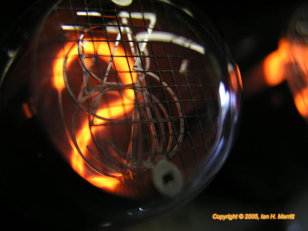
A closer look at a nixie tube.

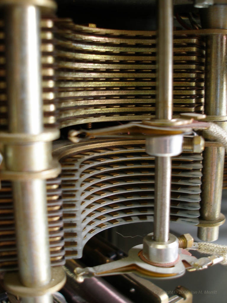
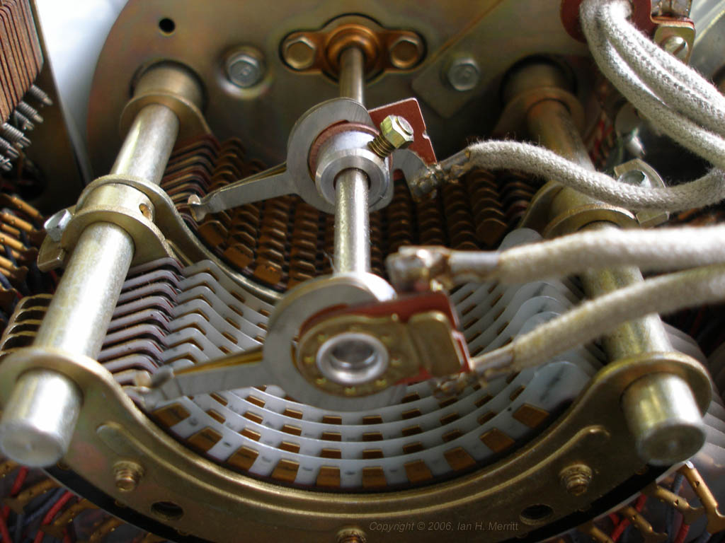
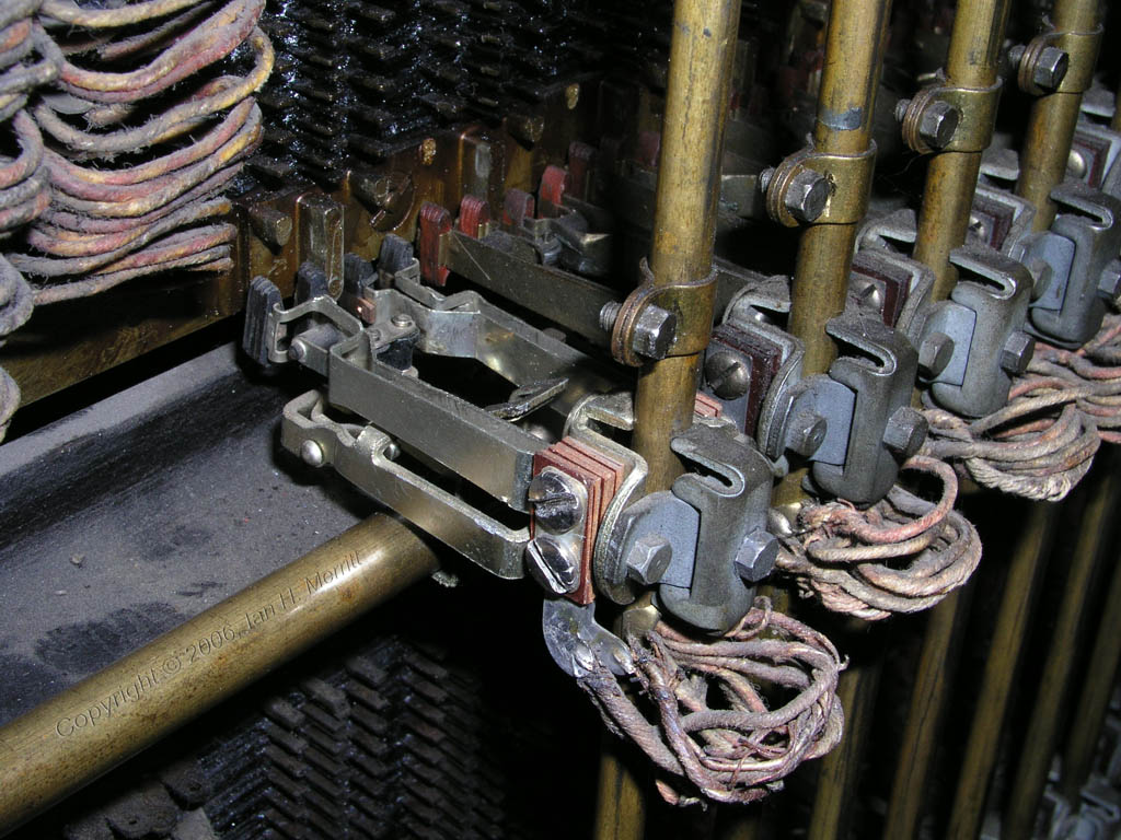
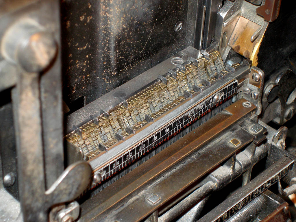
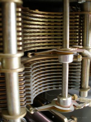
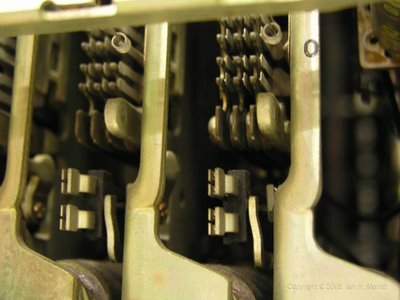
Part of a Panel switching matrix. The brass bars move slowly up until they reached the desired level; then the appropriate set of contact calipers engages with contact tabs protruding from the panel array behind it. Where crossbar and step were primarily driven by solenoids, this system used a central drive motor and a series of clutches to engage and disengage various parts when movement was required.

Close-up of the contact calipers that engage the panel contacts.